The Diagnostics Module
The Diagnostics module can be used to inspect system performance in both numerical and graphical presentations.
The following diagnostics are available:
CPU
Shows the processor ID, the number of (virtual) cores and usage of all CPU cores as well as the average CPU usage. If core usage exceeds 95% the graph will be red. A dark green graph indicates how the audio engine is performing, where 0 means it has 100% headroom and 100% means it is unable to keep up. Typically this line will be under 1%.
Memory
Shows memory usage of VidBlasterX.
Audio
Shows the audio's latency, under- and overflows for the selected source (like AV Recorder). The latency is shown in ms and is corrected for any intentionally added latency for buffering and/or delay correction. Typically this value should be near 0 ms. Under- en overflows relate to corrections in the audio buffer and are displayed a a red line going down (underflow) or up (overflow) from the vertical middle of the graph. Ideally under- and overflows should never happen.
Video
Shows the video's time stamp delta and -delay and, for modules like NDI Input that use a PLL, the delta sigma for the selected module. The time stamp delta, plotted in green, is the increase in the video frame's time stamp, or in other words the duration of a video frame, measured at the output of the selected module. When the time stamp is not available (missing frame), a vertical red line is shown. The time stamp delay (yellow) is the difference in the video frame's time stamp between the input and output of the selected module, i.e. the time it takes the module to process the video frame. Where available the time stamp delta of the source (Camera) or buffer size (NDI) is displayed in dark green. Delta sigma (dark grey) is the amount of compensation the PLL requires to lock onto the input clock. If SyncLok is enabled, a light grey line at the bottom will indicate SyncLok is achieved. The vertical scale is in milliseconds (ms), horizontally each pixels represents one video frame.
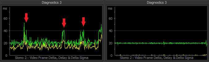
Even the most basic two-line video diagnostic is extremely informative, it shows the system's stability, video jitter and clock accuracy and indirectly the performance of each module and the underlying hardware. The example above shows the video diagnostic of a Slomo module running at 50 fps, so each frame lasts 20 ms. On the left you can see processing of a single frame (yellow line) takes about 12 ms on average, with spikes over 20 ms. The frame times (green line) are mostly 20 ms, but there's heavy jitter and during aforementioned spikes a frame is lost and the frame time doubles to 40 ms. Clearly this module is not up to its job and dropping frames. On the right the exact same setup but on a more powerful system. Note how the processing time of a frame is around 1 ms, resulting in a clean almost jitter free video signal. This module will not drop frames nor is it likely to ever do this considering its headroom. Using diagnostics you can guarantee your system is operating to broadcast specifications and spot any issues long before they are visible to the naked eye.
Phase
Shows the phase difference between the selected source and the selected Reference. The digit in the center of the meter indicates the number of "turns" (i.e. frames) the meter has made from zero.
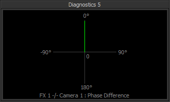
Above image shows a diagnostic with the phase vector steady at 0 degrees, indicating the FX 1 bus is synchronised to Camera 1.
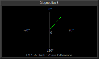
Here the phase vector is slowly rotating clockwise, indicating the FX 1 bus is not synchronised to the Black video signal (internal master clock).
Logic
A diagnostic similar to a logic analyser that can capture and display logical data of up to three sources based on a trigger event. Currently the logical data taken from a module is its frame clock, where an odd frame number is represented by a 1 and an even frame number by a 0. If no trigger pin is selected a transition from 0 to 1 in the first source (Module 1) will be used as a trigger. Currently supported triggers are the Video Switcher's ProgramBus and PreviewBus pins.
Data
Currently only supported by the Streamer module, this graph shows the stream's bit rate for the selected module. The vertical scale is in megabits per second (Mbps), horizontally each pixels represents one seconds
Right click the module to get access to its popup menu with the following entries:
Module
Module 1
Module 2
Module 3
Select the module that will be used as source for the diagnostic.
Reference
Select the module that will be used as reference for the Phase diagnostic.
Trigger
Select the module that will be used as trigger for the Logic diagnostic.
Copy
Makes a screen shot of the module and copies it to the clipboard.
Save As
Makes a screen shot of the module and saves it to disk.
Note the availability of menu entries varies with the diagnostic selected. Also note that, to save resources, diagnostics that are not selected will not be updated. If you require two or more diagnostics to be updated and/or visible at the same time, use one Diagnostics module per required diagnostic.