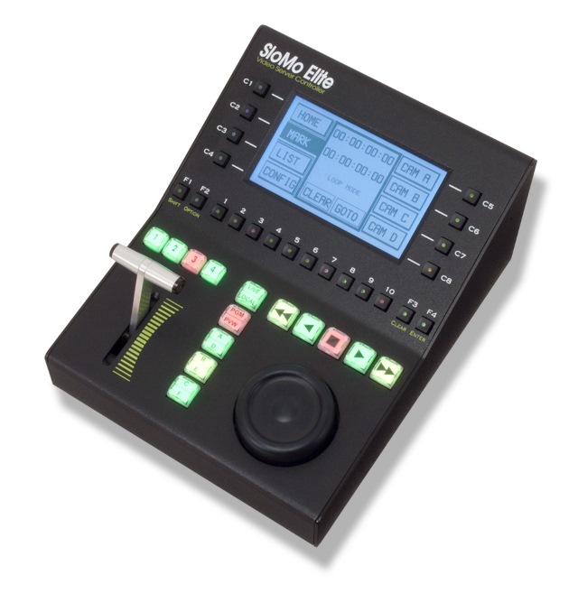
JLCooper Slomo Elite C controller
Until JLCooper starts offering a VidBlasterX edition of this controller you will need to recap some of the controller's buttons. This can be done quite easily using this (Word) template, transparent (overhead projector) sheets and a laser printer. As the horizontal row of player buttons has etched caps they cannot be used. Instead use the spare set of button caps you received with the controller (if you did not receive them JLCooper will ship them to you free of charge).
This controller requires the JLCooper I/O module to be loaded. Connect the controller to your network through its ethernet port (USB is not supported). To configure the controller, power it on while pressing down both the F1 and C4 buttons. Make sure to set it to Client mode. (Instructions how to setup a direct connection between your controller and PC is given below.) Finish by pressing the controller's Enter button. It should now connect to VidBlasterX. A warning may be given that you firmware is old. The latest firmware for this controller and an upload utility can be downloaded from the Developers section on the JLCooper web site.
1 2 3 4
Select "camera angle", i.e. which Slomo module is used for program or preview video.
Clear
Used to clear settings like in & out points. Activate this function by pressing once, the light will turn yellow.
IN
Marks in point. Use Shift > IN to go to in point. Use Clear > IN to clear the in point.
LIVE
Returns to live video. Any in & out points will be cleared, use Shift > LIVE to skip this step.
OPTION > export clip
Exports IN/OUT selection for the current camera angle as compressed video file to the Clip Export Folder set in the Slomo modules.
OUT
Marks out point. Use Shift > OUT to go to out point. Use Clear > OUT to clear the out point.
PLAY
Plays from current position at 100% speed.
PVW
Select preview mode. Clear > PVW will sync preview timecode to program timecode.
Shift
Used to access secondary commands like go to in & out points. Activate this function by pressing once, the light will turn green.
TAKE
Performs a take.
Button colour codes are yellow (available) and red (active). Camera selection buttons use green for PVW and red for PGM.
Creating a direct connection between controller and PC
Typically the controller will be connected to a network, but for small productions it may be preferable to connect the controller directly to the VidBlasterX PC with just an ethernet cable. If you have no experience in this, the list below of instructions below may be used as a guide.
1. The default setting for an ethernet port is DHCP. If there is no DCHP server offering you an IP, a random self assigned IP in the 169.254.x.x range will be used. This is not very suitable in our case, as we want full control of the IP in order to be able to tell the controller where to connect to. Best thing to do here is to assign a static IP address for the port in the 192.168.x.x or 10.x.x.x range, e.g. 192.168.1.10.
2. Either disable Windows firewall for the ethernet port or create a firewall rule allowing communication with the controller.
3. Set the controller to Function as a Client.
4. Set the controller's DESTIP Address and DEST Port Numb to the IP address and port number of the ethernet port (this is displayed in the JLCooper I/O module).
.
5. The IP of the computer and the controller need to be different, but in the same subnet. So for the controller's IP Address enter e.g. 192.168.1.11.
6. Change the subnet mask on the controller to 255.255.255.000.